Read the software progress log
Click image for larger version
Read the software progress log
Click image for larger version
Much more recently, I discovered that several companies offer small-scale PCB production services on-line, directly from CAD files. You send them a CAD file, they send you back a PCB (for a reasonable fee). Good electronic and PCB CAD programs are available for Windows, Linux and MacOS. With a PCB, I could add much more interesting I/O devices without making the construction too daunting.
With the arrival of eBay, unusual and obsolete chips are once again available, at least in small quantities. I was able to find a few more 68B09s (made by ST Microelectronics) and some 6551 serial port chips (made by Rockwell, whose semiconductor division became Conexant in 1999).
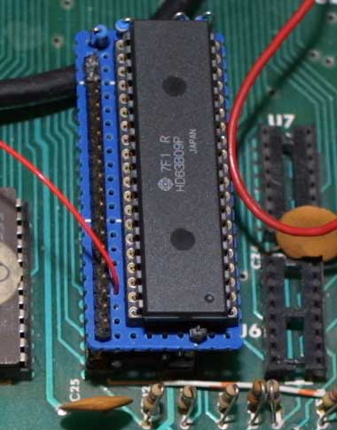
But another short-cut occurred to me: convert an existing 6502 machine to a 6809 CPU. I happened to have a non-working UK101 which seemed like a good choice. I'd been given the machine a few years ago by a work colleague who had built it from a kit, but it now had a dead mains transformer. So, first of all, I had to fix the power supply; the easiest option was to replace it with a modern switch-mode version.
I fixed up a few other parts of the UK101, like the video output cable. That had snapped off, so I soldered in a new one so that I could avoid the rather naff RF modulator. I also took each of the EPROM chips out of the UK101 and saved its contents into a file, via my trusty old Stag PPZ EPROM programmer. I didn't want to make any irreversible changes to the UK101, and a backup of the EPROMs seemed like a good idea. The UK101 worked fine as a 1MHz 6502 machine once the power supply was sorted out.
If you place a 6502 pinout and a 6809 pinout side-by-side, you'll notice that they have more than a few similarities.
So now I had a 6809 processor, but the UK101 still had 6502 EPROMs. Time to get out the 6809 assembler and write a little test program to just display "Hello, World" or something, and then get it into a 2716 EPROM. Should be easy, right? Well, first of all, the 6809 assembler generates a hex file in Intel hex format. I'd got the EPROM programmer set to accept MOS Technology format, which is what a 6502 assembler would generate. Proper 6809 assemblers would generate Motorola S-Records, but no, this one's giving me Intel format. OK, reconfigure the EPROM programmer.
But the programmer still won't accept the hex file. It gives me an error message about "not a hex character". A quick glance at the Intel format hex file revealed that the assembler was generating all the hex digits A-F in lower case. The Stag PPZ didn't like that, and wanted upper case. A quick pass through the traditional Unix 'tr' program fixed that one (for now; maybe fix the assembler one day).
To actually send the file to the EPROM programmer, via a serial cable, I'd been using the Linux terminal program 'minicom'. This is an interactive program that does various things like setting up a modem and transferring files. I was getting a bit fed up with setting the line speed to 9600 baud and turning off hardware handshake each time I sent a new hex file, so I thought I'd write a little Bash shell script to configure the serial line and send the file automatically. Setting the serial line is done with 'stty' and that worked OK, but the PPZ was now ignoring my hex file, when it worked fine via 'minicom'. The trouble was that Linux, like Unix, stores text files with a single character (line feed, ASCII value 10) as end-of-line. The programmer was expecting a carriage return at the end of each line (ASCII value 13). So, it's back to 'tr' again to fix that one.
Easy! Just connect the 6809 clock input to a pin on the UK101's clock divider chip. Pick a 4MHz output and we're done, right? Not exactly. The particular UK101 I'm using has a defective chip in that part of the circuit (it's a 7493, IC29) and the 4MHz output isn't working. I didn't know that at first, of course. Fortunately, I have a big pile of test gear right next to the UK101 and the 'scope soon sorted out the trouble. I'd fitted a 68B09 chip, which can accept an 8MHz master clock and produce a 2MHz 'E' signal, so I just used the UK101's 8MHz clock directly.
It worked! I got my "Hello, World" on the UK101's VDU as soon as the clock was sorted out. I sat there for a while, pressing reset on the UK101, and seeing the message appear on the VDU. OK, so I'm easily amused.
Return to John Honniball's Computer page
Return to John Honniball's home page
Copyright © 2004-2021 by John Honniball. All rights reserved.