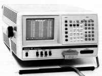
 This fine old logic analyser is a classic computer in its own right,
since it's powered by a Motorola
6800
CPU chip (the same chip as the
Tektronix 833 comms tester).
Shame it doesn't work at the moment.
Gould Electronics
| Old Sad Instruments |
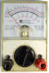
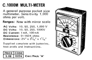
My very first multimeter. Acquired from Henry's Radio on the Edgware Road in London. Made in the 1970s and still in use today. I've had to repair and modify it, but it's still a useful instrument, even though its sensitivity is only 1000Ω/Volt. This means that it draws 1mA from the circuit you're testing, whereas a quality multimeter like an AVO Model 8 would only draw 50μA. Note the rather oversized 4mm terminals, installed in place of the original 2mm sockets that finally wore out a few years ago. I also wanted to make the meter fit my other test leads, which are all fitted with 4mm plugs. Also visible are two Allen bolts that hold the internal PCB in place. The original self-tapping screws (into plastic) had long since pulled out, leaving the range switch loose. So, at the same time as fitting the 4mm sockets, I drilled out and fitted the bolts. At some stage in the past (I don't remember when) the rectifier for AC voltage ranges failed, so that's now been replaced with a pair of point-contact diodes. A single AA battery powers the Ohms range. The original Henry's Radio advert shows that the price was £5.08.
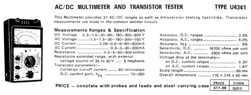
A Russian multimeter sold by Henry's Radio of Edgware Road in the 1970s. I still have this meter, but haven't photographed it yet. The price shown in the original Henry's Radio advert was £11.88.
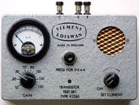
An early semiconductor tester that can only test PNP transistors. Bipolar transistors are made in two types, NPN and PNP, and the difference is in the polarity of the DC power supply to the device. This tester has no polarity-reversing switch, and can therefore only test PNP devices. In modern electronics, NPN is by far the more common type, but in the 1950s for some reason, PNP was more commonly used. I have another (presumably newer) tester that is fitted with a switch for NPN as well as PNP mode.
The tester is powered by the now-obsolete PP4 battery which was cylindrical, 9V, with a press-stud on each end. There's a clip inside the instrument to fit around the cylindrical body of the battery. These batteries are also known as Vidor VT4 and Ray-O-Vac 1600, although the ANSI designation is 6F24. They're now available only from specialist suppliers, and even then they're very expensive. Siemens Ediswan
This transistor tester, and the AVO Transistor Tester TT169, are shown on another page, the Ancient AVOs page.
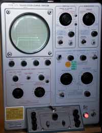
If you really want to know about a transistor, this is the instrument to use. It displays the characteristic curves of the transistor on a cathode-ray tube, just like an oscilloscope tube. It can test the transistor up to 400 Volts and 10 Amps, and even more with the add-on range extender. It's quite easy to set the tester up to show thermal runaway in germanium transistors. Apart from transistors, the instrument can test rectifier diodes and zener diodes.
Unlike the little Siemens test set, the Tek 575 is switchable for both PNP and NPN transistors. It has two transistor sockets on the sloping panel at the bottom, along with a switch to rapidly swap them over for comparison testing. This is how matched pairs of transistors were matched, before the process was automated.
Internally, the Tek 575 is a hybrid valve/transistor instrument, and even includes some matched-pair valves (vacuum tubes). The instrument was introduced in March 1957, just ten years after the invention of the transistor at Bell Labs. My example was built at the Tektronix factory in Guernsey, in the Channel Islands. It's built in the same size case as many of the Tektronix oscilloscopes of its generation. The case is so big and heavy that it has two carrying handles on top, implying that it's a two-person lift. There's a big AC-powered fan on the rear panel for cooling, and a filter which must be cleaned regularly (as the old Tek manuals used to say).
Basic Testing of Semiconductor Devices
and other information including Introduction to Curve Tracers
Tek 575 on the Tek Wiki.
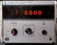
Nice little digital counter and frequency meter with nixie tubes. Circuits based on I.C.s, probably TTL. Also has a rear-panel connector for interfacing with a computer, although it pre-dates the HP-IB or IEEE-488 standards. The instrument division of HP is now known as Keysight.

Another digital counter and frequency meter with nixie tubes. The instrument division of HP is now known as Keysight.

Lovely set of logic debugging tools by the master of test gear, HP. The three probes are (top to bottom) the 546A Logic Pulser, the 545A Logic Probe and the 547A Current Tracer. The tapered device on the left is the 548A Logic Clip. The instrument division of HP is now known as Keysight.
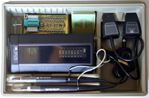
Another, older set of logic debugging tools in a handy plastic carrying case. The main tool is the 10529A Logic Comparator, complete with plug-in personality modules for various logic chips, a universal module and a self-test module. The two probes are (top to bottom) the 10526T Logic Pulser and the 10525T Logic Probe. Again, the tapered device on the right is a Logic Clip, the 10528A. The manuals for the kit are dated 1973. The instrument division of HP is now known as Keysight.
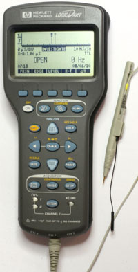
A much newer and more sophisticated device for logic debugging is the HP LogicDart. This is one of my favourite HP gadgets, a hand-held logic analyser and tester with an LCD display and three input channels. In fact, it's the only LCD that you'll find on this page! Until I add the Fluke 37, 8022, 8060, 8010 and 8050 that is. It'll also measure voltage and frequency, as well as having a continuity beeper and diode tester. Runs on three AA batteries. On the bench, the LogicDart can be powered by a 12V 100mA supply, but beware: the connector is wired centre negative. The Logic Dart was discontinued in 2004. The instrument division of HP is now known as Keysight.
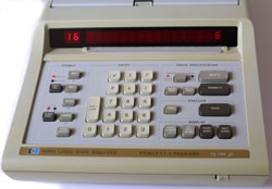
The 1602A is an early type of logic analyser, dating from 1978. It does not have a CRT display (as the later analysers did) but it just uses a row of seven-segment LED displays (made by the HP component division). In common with most HP kit of that era, the PCBs inside are fully gold-plated. The instrument division of HP is now known as Keysight.
The 1615A logic analyser features a CRT display and a hex keypad.
The 1630G logic analyser is a more sophisticated model than the 1615A, with more channels and more memory. Again, it has a CRT display and a hex keypad, but it also has a number of other control buttons.
This instrument represents the end of an era in logic analysers, because its complexity has reached a practical limit. There are so many connections to be made to the device you're testing that the wires are just too bulky. The introduction of JTAG ports has made analysers on this scale a thing of the past. The machine runs HP-UX and requires a PS/2 mouse and keyboard, and a VGA display. All the analyser functions are shown on an X Windows desktop. I think the processor in this instrument is a PA-RISC chip. My example has two of the optional 2GSa/sec analog oscilloscope boards (HP 16534A). On the rear panel are connectors for an external SCSI hard disk and an ethernet LAN connection.
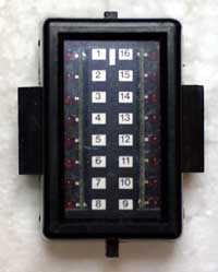
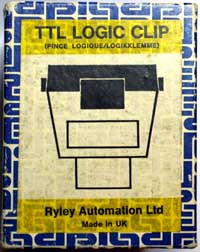
Rather like the HP548A Logic Clip, this is a UK-made gadget for testing the logic levels on DIL chips. It just clips over the chip and displays the logic levels on 16 red LEDs. Useful only for static or slowly-changing signals! This model has the handy feature of a slider that can be set to show the IC pin numbers for either 14-pin or 16-pin chips. In the 14-pin mode, the bottom two LEDs are covered up with a black shutter. I got this one from FreeCycle, complete with its original box and instructions.
 This fine old logic analyser is a classic computer in its own right,
since it's powered by a Motorola
6800
CPU chip (the same chip as the
Tektronix 833 comms tester).
Shame it doesn't work at the moment.
Gould Electronics
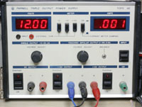
A very standard bench power supply from Farnell. It has three outputs, one for digital logic 1.5-6V, 3A and two for analog circuits, ±2-19V, 0.8A. The two analog supplies are tracking; that is, they are controlled by a single knob (the right-hand one) and are always equal in voltage but opposite in polarity. Each supply has a separate toggle switch (black plastic rectangles in the photo) that allows the user to first set up the supply with just the mains on, then switch on the output(s) when required. Of course, they're also handy for switching off in a hurry when things go wrong! The logic supply's ground is separate from the dual analog ground, which is separate again from mains earth (which is connected to the green socket on the front panel). All the terminals are 4mm sockets — see this page for some info about making up leads for it.
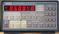
This device is an accurate source of DC voltage. The desired voltage is set up either by the front panel controls or by using the HP-IB (IEEE-488) interface. You can set up a sequence of voltage settings and time delays, so that the instrument will go through a cycle of output voltages. The current available is much less than you'd get from a power supply unit, only a matter of a few tens of milliamps. Maximum voltage is around 100V. One slight snag, though, is that the output terminals are on the back of the instrument, next to the HP-IB (IEEE-488) port. Housed in the same brown case, and with the same colour scheme as the 195 Systems DMM. Keithley Instruments.
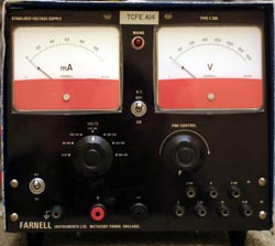
A typical modern bench power supply might have a 0-6V output and maybe a pair of 0-18V outputs. The E350 has a single 0-350V output at a maximum of 100mA. It also has a selection of valve heater outputs, which rather gives away its age. The heater outputs are 3.15-0-3.15V at 2A and 0-2.5-5-6.3V at 3A, all AC of course. The circuit is hybrid, with a selection of semiconductor diodes and transistors as well as an EL34 valve (vacuum tube).
 Another instrument that's powered by a classic computer, this time
the Motorola
6809.
The machine was built in 1984, according to the dates stamped inside.
I have two plug-in modules for the universal programmer mainframe,
the Zm2200 for PALs and the Zm2000 for PROMs and EPROMs.
In fact, I have two versions of the Zm2000, one with Revision 36
firmware, the other with Revision 37.
I'd be keen to find some other plug-ins, or even just to find a
full list of what plug-ins were available for this machine.
I've seen a Stag "Product Selection Guide" that lists the
Zm2300 Super PLD Module, the Zm2500 MOS Module, the Zm2800
Gang/Set Module and the Zm29xx Custom Module.
Were there any others?
I do know that there was a successor machine to the PPZ, the
Stag System 3000, which accepts the Zm3000 module.
I regularly use this programmer for reading and programming EPROMs,
such as the 2716 EPROMs used in the
Compukit UK101.
I've also used it to write 2716 EPROMs with 6809 code for use in a
modified UK101, fitted with a 6809 CPU.
More recently, I wrote some 27C128 EPROMs for a 6309-based
single-board computer that I bought from eBay.
The Zm2000 Module will also read and program bipolar PROMs,
which was useful when I wanted to work with PDP-11 boot PROMs.
Some more photos of the PPZ are in this
Flickr set.
Matthieu Benoit's Stag PPZ resources page
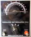
I was given this little RF signal generator when I visited the Denco factory in Clacton in the 1970s. It has a single valve (Mullard DL92) and requires a special battery to supply both HT and heater voltages. The frequency ranges are 170-475kHz and 550-1600kHz, which covers the Medium Wave band nicely.
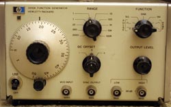 A very fine HP function generator from 1979.
Contains a mix of discrete transistors and metal-can ICs (741 op-amps)
on PCBs that are gold-plated all over.
The gold plating was probably done to improve the solderability
of the board, leading to better reliability, but it also makes the
insides of these older HP instruments look so much prettier.
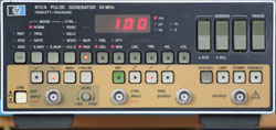 A comparatively modern HP digital pulse generator.
This one is quite fun to set up as a variable mark/space ratio
PWM
generator, and then control LEDs or motors with it.
All the controls are push-buttons on the front panel, and remote
control is possible via the rear-mounted HP-IB (IEEE-488) interface.
Another HP instrument that I just couldn't resist.
It's a 6½ digit DVM that looks really impressive in a stack of test equipment.
The 3456A was designed without compromise for accuracy — it's not intended
for use outside the lab environment.
The instrument has an HP-IB (IEEE-488) interface and must be mains powered.
It has the distinction of being able to make resistance measurements using a
Kelvin connection
(four-wire Ohms range).
However, it can only measure voltage and resistance; it has no current ranges.
Seems a bit silly to use it to test the AA batteries in the TV remote control...
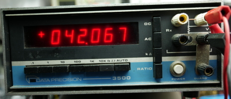 5½ digit bench multimeter with voltage and resistance ranges.
Featuring the beautiful Panaplex display.
Once again it has a
Kelvin connection
(four-wire Ohms mode).
Big row of relays inside that select ranges and click nicely in auto-ranging mode.
BCD digital output connector on the back.
I actually have three of these meters and occasionally use them.
For more photos, see this Flickr album:
Data Precision 3500 Multimeter (2).
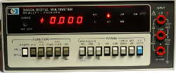
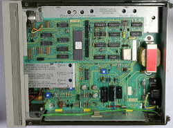 4½ digit bench multimeter with voltage, current and resistance ranges.
Ingenious fuse-holder built in to the bottom 4mm socket.
Although my example doesn't have it, an internal battery option was
available for this instrument.
This meter lives on the workbench and actually gets used to measure stuff.
 I just couldn't resist this one when I saw it.
What a great example of Sci-Fi styling!
Unfortunately, the built-in NiCad batteries are in poor condition now.
Another fine example of HP kit from the 1970s, the era of the gold-plated PCBs.
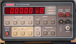 Another bench DMM, this time with DC and AC current ranges (AC current was an optional
extra).
It's small enough to be used away from the bench, but has no batteries and consequently needs
a mains power supply.
Like many instruments here, it has an HP-IB (IEEE-488) interface on the back.
This instrument, like its counterpart, the
230 Programmable Voltage Source,
is housed in a snazzy brown plastic case and has a truly 1970s colour scheme.

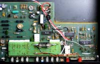
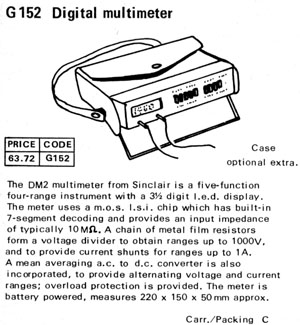 Another multimeter, but this time a British one, by Sinclair.
Once again, a 3½ digit DMM with LED display.
The main chip is an AY-5-3507, date coded 7706 (week 6 of 1977).
The case is made of quite thick steel, painted black all over.
The black carrying case with shoulder strap was an optional extra,
which was supplied with my example of this meter.
There's a socket on the back for a mains adaptor, which will also charge
the internal batteries, if fitted.
The Henry's Radio advertisement shows that the price was £63.72, rather
expensive for a multimeter at the time!
My simple analog meter (at the top of this page) was only just over a fiver.
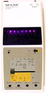 Another Sinclair multimeter, a few years later than the DM2.
It's housed in the same case as a Sinclair Oxford calculator, as is the PFM200A
frequency meter.
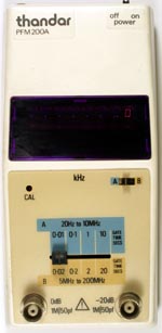 Again housed in a calculator case, this is Sinclair's frequency meter, re-badged
as a Thandar.
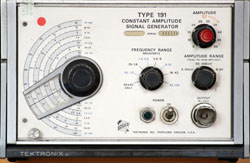 RF signal generator featuring a bizarre
GR874
hermaphrodite connector.
Hybrid circuit with both valves and transistors, introduced in 1966.
It covers the frequency range from 350kHz to 100MHz.
The “constant amplitude” just means that there's no
provision for amplitude modulating the signal.
In fact, the output amplitude is regulated by a special circuit inside
the signal generator and is adjustable only in calibrated steps.
This makes these signal generators useful as scope calibrators.
At last, I have an
adaptor
to plug into the GR874 connector to convert it into the rather more useful
BNC
socket.
Now all I need is another mains cable with the US 3-pin connector on the end,
so that I can power it up without having to unplug the
Tek 564B scope.
Tektronix.
Tek 191 on the Tek Wiki.
Amazing piece of technology incorporating a punched-card programming arrangement to set the tester up for each type of valve. There's also a lever, not unlike a fruit machine, to lock the punched card in place and start the test. The display is on a CRT, which is really under-utilised and could have been replaced by a simple meter — the machine was built by Mullard, though, and they make CRTs! One of the punched cards is a self-test card. Probably built in the 1950s. Another valve enthusiast's valve tester page.
A nixie tube instrument.
Seems to work by converting the incoming voltage into a frequency,
passing it through a transformer (for isolation), and then measuring
the frequency.
I occasionally take this instrument out to shows to demonstrate the nixie
tube display.
Here are photos taken at Tech Adventure in Bristol,
2008
and 2009.
Solartron LM1420.2 at Radiomuseum
Solartron.
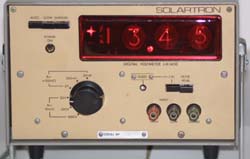 Another nixie tube instrument,
like the LM 1420.
Photos of the interior of the voltmeter
Solartron.
 A very fine old valve signal generator.
Dymar merged with Burndept, then bought by FKI.
Made radio sets for emergency sevices and public utilities.
Dymar Type 741 at Radiomuseum
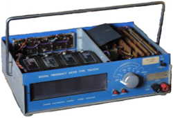 A digital frequency meter based entirely on discrete transistors.
They seem to be mostly Mullard OC44 and OC45 types.
The display is four digits, using the E.A.C. Digivisor.
The Digivisor is a moving-coil device which projects the image of
a digit onto a screen, according to the current flowing through it.
Each digit display is driven from a digital-to-analog convertor,
and the adjustments for these DACs are brought out the the rear
panel (two adjustments per digit).
Unfortunately, the instrument had been thrown out,
and had had the mains lead cut off flush with the rear panel.
I have replaced the lead,
even though it meant taking apart almost the entire power supply section.
I can now power up the frequency meter,
and see the displays light up,
but they still don't work properly.
My video of the display lighting up.
Mike's Electric Stuff on the Venner TSA3336
Venner TSA3334 at Radiomuseum

More nixie tubes than you can
shake a stick at!
The front panel lights up in a rather gratuitous manner, too.
The function of this device is a bit obscure, but it seems
to combine a swept signal generator with an AC millivoltmeter,
so that it can measure the frequency and phase response of an
amplifier.
This one doesn't work at present, due to a short of some kind on the
internal power supply.
I think this is likely to be due to a shorted tantalum capacitor,
but of course locating that capacitor will be tricky.
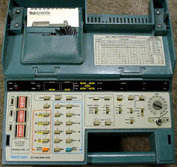 In the days before
LANs and packet sniffers,
data communications
were usually just simple RS-232 links, and the Tektronix 833 was
designed to debug them.
It's based on a
Motorola 6800
processor and it has switch-selectable baud
rates from 50 to 9600, including the IBM Selectric speed of 134.5 baud.
It has a built-in RS232 break-out box and can transmit and receive
test messages in
ASCII and
EBCDIC.
The display is a seven-segment LED, showing codes in hexadecimal.
This was not a cheap instrument; in 1982, the list price was $2750.
Tektronix.
Tek 833 on the Tek Wiki.
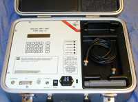 Technology moves on, and we go from RS-232 to Ethernet.
This instrument is packaged in a fine little metal suitcase
and can be used to test both Ethernet transceivers and complete
Ethernet installations.
In fact, it's best suited to the so-called Cheapernet,
or thin Ethernet, system because it has a BNC socket for
the network connection.
It's no good for twisted-pair Ethernet systems, nor can it
deal with 100Mb or 1Gb networks.
Return to the Old Sad Things page
Return to John Honniball's home page
Copyright © 1997-2021 by John Honniball. All rights reserved.