Some of the more unusual parts, old and new, from my collection.
Panaplex Displays
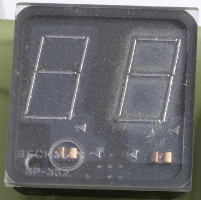
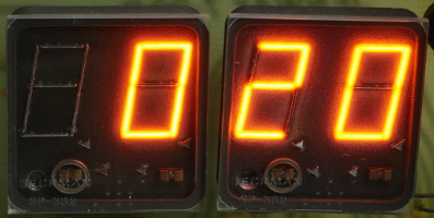 Panaplex displays, like Nixie tubes,
are basically neon lamps, but with the electrodes arranged as seven segments.
High-voltage driver chips were available to interface between 5V logic,
such as a 7-segment decoder,
and the Panaplex display.
They were popular in test equipment like multimeters and frequency counters,
and also appeared in consumer electronics such as calculators and clocks.
The calculator displays were generally smaller and sometimes combined eight
Panaplex digits into a single glass envelope.
For more photos of Panaplex displays, see this Flickr photo group:
Panaplex Displays.
Panaplex displays, like Nixie tubes,
are basically neon lamps, but with the electrodes arranged as seven segments.
High-voltage driver chips were available to interface between 5V logic,
such as a 7-segment decoder,
and the Panaplex display.
They were popular in test equipment like multimeters and frequency counters,
and also appeared in consumer electronics such as calculators and clocks.
The calculator displays were generally smaller and sometimes combined eight
Panaplex digits into a single glass envelope.
For more photos of Panaplex displays, see this Flickr photo group:
Panaplex Displays.
TIL311 Hex LED Display
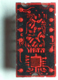 A numerical display comprising a seven-segment
LED
display and a binary decoder chip.
The chip (at the bottom of the package) accepted four binary bits,
representing a number from zero to 15.
It then displayed that number on the LEDs, using the hexadecimal digits
A-F for the (decimal) numbers 10 to 15.
Parts like this caused the demise of the nixie tube (above).
For more photos of old displays, see
The Vintage Technology Association.
A numerical display comprising a seven-segment
LED
display and a binary decoder chip.
The chip (at the bottom of the package) accepted four binary bits,
representing a number from zero to 15.
It then displayed that number on the LEDs, using the hexadecimal digits
A-F for the (decimal) numbers 10 to 15.
Parts like this caused the demise of the nixie tube (above).
For more photos of old displays, see
The Vintage Technology Association.
Semiconductors In Coloured Epoxy
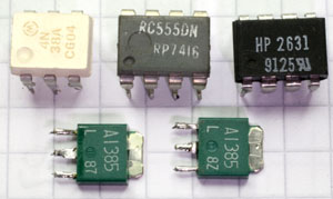
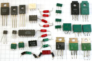 Normally, chips, transistors and diodes are packaged in black
epoxy
for protection from the environment, especially from corrosion due to moisture.
But these chips are clearly not in black epoxy, but white, grey
and green (there's a black one, too, for comparison).
Going from left to right (in the right-hand photo), there's a 4N38A optocoupler (white),
an RC555DN timer (grey), an HP2631 dual optocoupler (black)
and in the bottom row, two 2SA1385 PNP transistors (green).
The grey 555 chip is date coded “7416”, meaning the 16th
week of 1974.
The left-hand photo shows even more colour variation: diodes in red.
The transistors show the common marking convention for Japanese parts,
in that the “2S” prefix is omitted.
I've seen a few other examples of power transistors in green epoxy,
and optocouplers are commonly in white epoxy.
Power transistors in grey are very common and not really peculiar
enough for this page.
Normally, chips, transistors and diodes are packaged in black
epoxy
for protection from the environment, especially from corrosion due to moisture.
But these chips are clearly not in black epoxy, but white, grey
and green (there's a black one, too, for comparison).
Going from left to right (in the right-hand photo), there's a 4N38A optocoupler (white),
an RC555DN timer (grey), an HP2631 dual optocoupler (black)
and in the bottom row, two 2SA1385 PNP transistors (green).
The grey 555 chip is date coded “7416”, meaning the 16th
week of 1974.
The left-hand photo shows even more colour variation: diodes in red.
The transistors show the common marking convention for Japanese parts,
in that the “2S” prefix is omitted.
I've seen a few other examples of power transistors in green epoxy,
and optocouplers are commonly in white epoxy.
Power transistors in grey are very common and not really peculiar
enough for this page.
But the real questions is why?
Why do semiconductor manufacturers offer optocouplers in white
(it's an ordering option on the datasheet)?
Why are power transistors sometimes green?
And are the green ones always PNP bipolar transistors or P-channel FETs?
High Stability Resistors
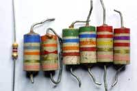 Special “High Stability” resistors with an extra pink band (sometimes
called “salmon”) to indicate their superior quality.
From left to right, a modern 4.7kΩ for comparison, a 68kΩ,
a 3.3kΩ, two 56kΩ, a 220kΩ and a 2.7kΩ.
All are 5% tolerance (gold band) apart from the 56kΩ, which
are 2% tolerance (red band).
The modern resistor is a metal film type, but the older ones are carbon
composition.
They were wax coated for moisture-proofing.
Special “High Stability” resistors with an extra pink band (sometimes
called “salmon”) to indicate their superior quality.
From left to right, a modern 4.7kΩ for comparison, a 68kΩ,
a 3.3kΩ, two 56kΩ, a 220kΩ and a 2.7kΩ.
All are 5% tolerance (gold band) apart from the 56kΩ, which
are 2% tolerance (red band).
The modern resistor is a metal film type, but the older ones are carbon
composition.
They were wax coated for moisture-proofing.
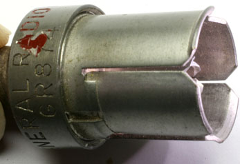
Plessey Castanet Capacitors
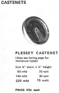 These capacitors were made by Plessey, probably in the early 1970s.
I have only one of these capacitors, removed from a surplus
PCB
many years ago.
The advertisement (with the spelling mistake) is by
Henry's Radio of Edgware Road, London.
These capacitors were made by Plessey, probably in the early 1970s.
I have only one of these capacitors, removed from a surplus
PCB
many years ago.
The advertisement (with the spelling mistake) is by
Henry's Radio of Edgware Road, London.
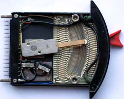
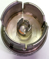
PAL Delay Line
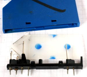 A PAL delay line, containing a quartz block and two transducers.
Now that analog TV using the European
PAL
system is becoming obsolete, we'll see fewer of these iconic components.
Every PAL TV had one, to act as an analog memory for one scan-line of
the TV signal.
One scan-line is equivalent to 64μs, and that's how long the delay line
was.
They worked acoustically, converting the electrical video signal into
vibrations in the quartz block, and then converting it back after the
signal had been reflected off the far end of the block.
In the photo, I've removed the blue plastic cover to show the internals
of the device.
A PAL delay line, containing a quartz block and two transducers.
Now that analog TV using the European
PAL
system is becoming obsolete, we'll see fewer of these iconic components.
Every PAL TV had one, to act as an analog memory for one scan-line of
the TV signal.
One scan-line is equivalent to 64μs, and that's how long the delay line
was.
They worked acoustically, converting the electrical video signal into
vibrations in the quartz block, and then converting it back after the
signal had been reflected off the far end of the block.
In the photo, I've removed the blue plastic cover to show the internals
of the device.
Rockwell Piggyback Chip
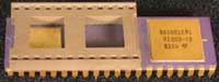 A Rockwell R65/11EB chip.
The socket on the back of the chip is for an
EPROM
to be fitted.
The EPROM would contain the code for the program under development,
and would emulate the mask-programmed ROM of the final version.
A Rockwell R65/11EB chip.
The socket on the back of the chip is for an
EPROM
to be fitted.
The EPROM would contain the code for the program under development,
and would emulate the mask-programmed ROM of the final version.
AM27256 EPROM Chip
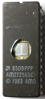
 This isn't all that peculiar, but it's now old enough that some people will
never have seen one in a computer.
It's a 27256
EPROM,
made by AMD in 1985.
This size of chip can store 256Kbits, organised as 32768x8bits.
EPROM chips are non-volatile memories, that is,
they retain their data even when the power is switched off.
They are erased by exposure to
UV light, which is the
reason for the quartz window in the top of the chip package.
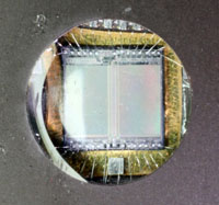
The irridescent colours visible in the close-up photo are due to the
features on the chip being small enough to act as a diffraction grating.
This isn't all that peculiar, but it's now old enough that some people will
never have seen one in a computer.
It's a 27256
EPROM,
made by AMD in 1985.
This size of chip can store 256Kbits, organised as 32768x8bits.
EPROM chips are non-volatile memories, that is,
they retain their data even when the power is switched off.
They are erased by exposure to
UV light, which is the
reason for the quartz window in the top of the chip package.
The irridescent colours visible in the close-up photo are due to the
features on the chip being small enough to act as a diffraction grating.
EPROMs have now been almost entirely superceded by Flash ROMs,
which are electrically erasable.
Knife Switch
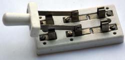
A porcelain knife switch, used for disconnecting an aerial (antenna)
from a radio receiver.
The two centre terminals of the switch are connected to the antenna
and the two left-hand terminals go to the radio.
Finally, the two terminals on the right are earthed.
The switch incorporates two spark-gaps which are intended to prevent
lightning from damaging the radio.
But the real protective measure is to switch the handle over to
the earthed position whenever the radio is not in use.
This disconnects the aerial from the radio, and connects it
directly to earth.
Quadrant Fader
On
BBC
mixing desks of the 1960s and 1970s, you'll find faders that
have a curved track, unlike the flat slider of more recent mixers.
These are quadrant faders, and they were built as professional-grade
devices for broadcast use.
The whole fader can be unplugged from the mixer for maintenance or
replacement (note the locating pins on the left-hand side).
It functions as an attenuator, with the slider selecting different
levels of attenuation at each step, although the steps cannot be
felt by the user.
The scale is marked in dB and is
illuminated by two small bulbs.
There are two microswitches, set to switch at the very ends
of the fader's travel.
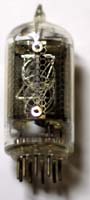
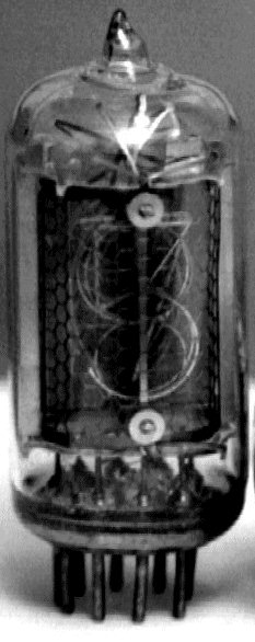
Magic Eye Valves
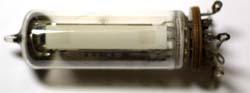
This example of a magic eye valve is a Telefunken EM84.
Magic eyes were used in valve circuits as record-level indicators,
tuning indicators and null indicators.
They work rather like a CRT,
in that they have a phosphor coating on the inside of the glass
envelope, which glows when struck by electrons.
In the CRT, the electrons are in a finely focused beam, but in the
magic eye, they cover a wide area.
Hence, a wide strip of phosphor will glow (green) when the valve
is working.
The length of the glowing strip is controlled by the voltage on
one of the electrodes inside the valve.
Much smaller valves were also made (DM160) that simply lit up,
and did not have any means to vary the size of the glow -- a sort
of digital version of the magic eye.
For more photos of old displays, see
The Vintage Technology Association.
Glass Envelope Crystal
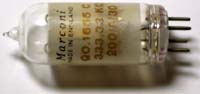 Crystal in glass valve-like envelope.
Modern quartz crystals are housed in metal cans, but this older
example is in a glass envelope.
Unlike a valve, it does not have a “getter”, a metallised
area around the top of the valve that chemically reacts with any
remaining air inside.
Therefore, it probably doesn't have a vacuum inside, but it may be
filled with an inert gas, such as nitrogen.
It was made by Marconi, and its frequency is 333.333kc/s (or kHz
in modern units).
Crystal in glass valve-like envelope.
Modern quartz crystals are housed in metal cans, but this older
example is in a glass envelope.
Unlike a valve, it does not have a “getter”, a metallised
area around the top of the valve that chemically reacts with any
remaining air inside.
Therefore, it probably doesn't have a vacuum inside, but it may be
filled with an inert gas, such as nitrogen.
It was made by Marconi, and its frequency is 333.333kc/s (or kHz
in modern units).
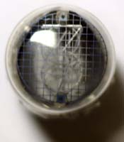
Glass Envelope Photoresistor
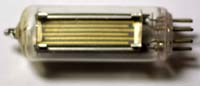 Photo-sensitive resistor in glass valve-like envelope.
This is a Mullard part, made in Holland, but the part number has
rubbed off (apart from the ORP prefix).
The gold fingers are the two electrodes that make contact with the
light-sensitive material inside the glass envelope.
Photo-sensitive resistor in glass valve-like envelope.
This is a Mullard part, made in Holland, but the part number has
rubbed off (apart from the ORP prefix).
The gold fingers are the two electrodes that make contact with the
light-sensitive material inside the glass envelope.
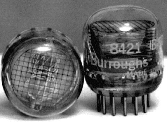
 Nixie Tubes were invented by Burroughs as a means to display numerical
information.
They are basically neon lamps, with the electrodes carefully
shaped to represent digits.
Some nixie tubes were made with symbols instead of digits,
usually A, V and Ω to represent Volts, Amps and Ohms respectively
(for use in electronic test instruments).
They were also sometimes called Numicators.
These displays seem to be getting popular again nowadays, as part
of the nixie tube clock.
One can buy kits of parts to build a clock with nixie tubes for
the display.
You can see some more detail in these
photos of side-viewed and
end-viewed nixie tubes.
For a contemporary description of nixie tubes, see the article in
Scientific American, Electronic Numbers, June 1973,
page 66.
For more photos of old displays, see
The Vintage Technology Association.
Nixie Tubes were invented by Burroughs as a means to display numerical
information.
They are basically neon lamps, with the electrodes carefully
shaped to represent digits.
Some nixie tubes were made with symbols instead of digits,
usually A, V and Ω to represent Volts, Amps and Ohms respectively
(for use in electronic test instruments).
They were also sometimes called Numicators.
These displays seem to be getting popular again nowadays, as part
of the nixie tube clock.
One can buy kits of parts to build a clock with nixie tubes for
the display.
You can see some more detail in these
photos of side-viewed and
end-viewed nixie tubes.
For a contemporary description of nixie tubes, see the article in
Scientific American, Electronic Numbers, June 1973,
page 66.
For more photos of old displays, see
The Vintage Technology Association.
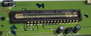
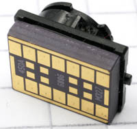 This is the image sensor chip and associated lens from a Nokia
7250i cameraphone.
It has 14 connections, arranged in two rows of seven gold-plated
square pads, on the back of the ceramic package.
It just plugs into a receptacle inside the phone.
For scale, the squares in the background are 5mm.
This is the image sensor chip and associated lens from a Nokia
7250i cameraphone.
It has 14 connections, arranged in two rows of seven gold-plated
square pads, on the back of the ceramic package.
It just plugs into a receptacle inside the phone.
For scale, the squares in the background are 5mm.