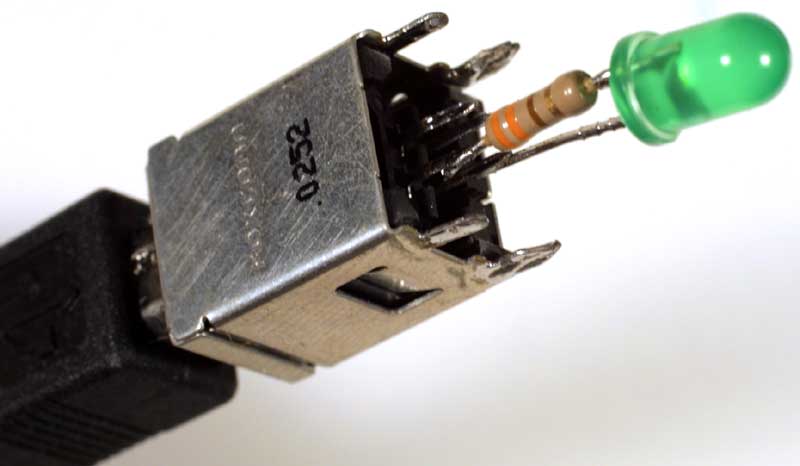
USB Power Control

HOME > Creative Technology > USB Power

USB LED
USB LED
John Honniball, 2006, lead and tin on copper with found components, 31mm × 12mm


So where does that get me? Well, I now know that most USB ports are powered from standby power, which means that they stay powered up even when the PC is switched off—so that the PC can be powered up by the keyboard, or by a mouse click. Which means that my simple approach to USB-controlled power isn't going to work, because it will simply be switched on all the time. A proper solution would require a microcontroller in the USB device, to interact with the USB controller and sense when the PC is switched from standby to fully on.

But I have a simple solution: plug the switch into an internal USB hub, which does not supply standby power.


Now for the mains (240V AC, 50Hz, 13A) switching part of the design. Introducing an inexpensive timer switch:
Time switch Time switch opened up Time switch with wires
So, what's inside the mains timer switch? It turns out to be very easily modifiable, with two internal PCBs, one for the clock/timer chip, display and buttons, and the other for the power switching. There's a little three-wire ribbon cable between them, with two wires to supply power to the clock/timer, and one to signal to the mains board to switch on the relay. Both boards are connected directly to the live mains, and are therefore not safe to connect to a USB port. To isolate the USB port from the live mains, I use an optocoupler that I desoldered from a scrap switch-mode power supply (SMPSU).

Return to the Creative Technology page

Return to John Honniball's home page

Copyright © 2006 by John Honniball. All rights reserved.