
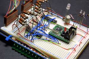
There are lots of designs on the web for persistence-of-vision LED displays, some with motors and some hand-operated. I happened to have a lot of green LEDs and some 18-core cable, so I made one up in the form of a hand-held wand. It has 16 LEDs soldered onto some square-pad prototyping board. The LEDs are driven through 220Ω resistors from a pair of 74LS373 latch chips. The resistors (which I got from the Bristol FreeCycle list) are on the upper left in the photo. The two chips underneath the blue wiring on the solderless breadboard are the 74LS373s, and the little green PCB module carries the Atmel ATmega8 microcontroller. The brown connectors on the far left of the breadboard go to the wand itself, via the 18-core cable. There are a few extraneous LEDs and transistors on the far side of the breadboard, where I was experimenting with PWM for controlling the brightness of some blue LEDs.
The software in the Atmel AVR chip is entirely written in assembler. The AVR is, like many microcontrollers, a Harvard Architecture machine, which means that it has separate memories for program and data. The program code is stored into the Flash memory by the AVRISP programming tool, while run-time data is stored into RAM by the processor itself. There's also some EEPROM on the chip, but this little program doesn't use it. The source code is here (ASCII text format, 8kbytes).
I rushed the software a bit to get it ready for a friend's birthday party; note the missing pixel on the bottom row! I fixed it shortly afterwards, and the photos taken at Dorkbot Bristol show the corrected version. Also, note the four unused LEDs at the top of the pattern. I have 16 LEDs, but I'm only using 12 of them for this pattern.
; pov.asm --- drive the POV LEDs                               16/04/2006
; Copyright (c) 2006 John Honniball

.include "m8def.inc"

            .org 0x0000

; Two 74LS373 latches on Port D bits 0-7
; Latch controls on Port B bits 0 and 1
; Control bit HIGH: transparent
; Control bit LOW:  latch
; Blue LEDs on Port B bits 2 and 3

; Block of interrupt vectors for the AVR ATmega8
            rjmp RESET                              ; Reset Handler
            rjmp EXT_INT0                           ; IRQ0 Handler
            rjmp EXT_INT1                           ; IRQ1 Handler
            rjmp TIM2_COMP                          ; Timer2 Compare Handler
            rjmp TIM2_OVF                           ; Timer2 Overflow Handler
            rjmp TIM1_CAPT                          ; Timer1 Capture Handler
            rjmp TIM1_COMPA                         ; Timer1 CompareA Handler
            rjmp TIM1_COMPB                         ; Timer1 CompareB Handler
            rjmp TIM1_OVF                           ; Timer1 Overflow Handler
            rjmp TIM0_OVF                           ; Timer0 Overflow Handler
            rjmp SPI_STC                            ; SPI Transfer Complete Handler
            rjmp USART_RXC                          ; USART RX Complete Handler
            rjmp USART_UDRE                         ; UDR Empty Handler
            rjmp USART_TXC                          ; USART TX Complete Handler
            rjmp ADCONV                             ; ADC Conversion Complete Handler
            rjmp EE_RDY                             ; EEPROM Ready Handler
            rjmp ANA_COMP                           ; Analog Comparator Handler
            rjmp TWSI                               ; Two-wire Serial Interface Handler
            rjmp SPM_RDY                            ; Store Program Memory Ready Handler

; Start of program execution after a Reset
RESET:      ldi r16,low(RAMEND)                     ; Initialise stack to top of RAM
            out SPL,r16
            ldi r16,high(RAMEND)
            out SPH,r16

            ldi r16,0xff                            ; Set Port B to all outputs
            out DDRB,r16
            ldi r16,0xff                            ; Set Port D to all outputs
            out DDRD,r16

            sbi PortB,2                             ; Switch off blue LEDs
            sbi PortB,3
            sbi PortB,4

            cbi PortB,0                             ; Set both latches to hold
            cbi PortB,1                             ; by setting PB0 and PB1 low

loop:       ldi ZL,low(2*pattern)                   ; Z register pair points to pattern
            ldi ZH,high(2*pattern)                  ; in program memory

            ldi r18,14                              ; Load pattern length

patloop:    lpm r16,Z+                              ; Load pattern byte from program memory (upper)
            lpm r17,Z+                              ; Load pattern byte from program memory (lower)

            com r16                                 ; Output bits are active-low
            com r17

            out PortD,r16                           ; Send to latches
            sbi PortB,0                             ; Latch 373 on PB0
            rcall delay2us
            cbi PortB,0                             ; Clear PB0 again

            out PortD,r17                           ; Send to latches
            sbi PortB,1                             ; Latch 373 on PB1
            rcall delay2us
            cbi PortB,1                             ; Clear PB1 again

            ldi r19,8
dly:        rcall delay1ms
            dec	r19
            brne dly

            dec r18                                 ; Decrement pattern length counter
            brne patloop

    	    rjmp loop                               ; Loop back to start


; DELAY2US
; Delay for 2 microseconds
delay2us:   ldi r24,low(8)
            ldi r25,high(8)
dly9:       sbiw r24,1                               ; 2 cycles
            brne dly9                                ; 2 cycles
            ret
; DELAY1MS
; Delay for 1 millisecond
delay1ms:   ldi r24,low(4000)
            ldi r25,high(4000)
dly8:       sbiw r24,1                               ; 2 cycles
            brne dly8                                ; 2 cycles
            ret

pattern1:   .db 0x00,0x01                            ; Greek Key 12 pixels
            .db 0x07,0xfd
            .db 0x04,0x05
            .db 0x05,0xf5
            .db 0x05,0x15
            .db 0x05,0x55
            .db 0x05,0x45
            .db 0x05,0x7d
            .db 0x05,0x01
            .db 0x05,0xff
            .db 0x04,0x00
            .db 0x07,0xff

pattern2:   .db 0x1c,0x00                            ; Heart 16 pixels
            .db 0x3f,0x00
            .db 0x7f,0xc0
            .db 0xff,0xf0
            .db 0xff,0xf8
            .db 0x7f,0xfc
            .db 0x3f,0xfe
            .db 0x1f,0xff
            .db 0x3f,0xfe
            .db 0x7f,0xfc
            .db 0xff,0xf8
            .db 0xff,0xf0
            .db 0x7f,0xc0
            .db 0x3f,0x00
            .db 0x1c,0x00
            .db 0x00,0x00

pattern3:   .db 0xf7,0xfc                            ; Celtic Key 16 pixels
            .db 0xf7,0xfc
            .db 0xf7,0xfc
            .db 0xf7,0xfc
            .db 0x07,0x80
            .db 0xff,0xbc
            .db 0xff,0xbc
            .db 0xff,0xbc
            .db 0xff,0xbc
            .db 0xf0,0x3c
            .db 0xf7,0xfc
            .db 0xf7,0x3c
            .db 0xf7,0x3c
            .db 0xf7,0x3c
            .db 0x00,0x00
            .db 0x00,0x00

pattern:    .db 0x00,0x04                            ; Space Invader
            .db 0x07,0x0c                            ; Designed at Dorkbot Bristol
            .db 0x0f,0x98                            ; by Kathy Hinde and Tarim
            .db 0x19,0xf0                            ; 14 pixels including gap
            .db 0x39,0xe0
            .db 0x3f,0xe0
            .db 0x3f,0xe0
            .db 0x39,0xe0
            .db 0x19,0xf0
            .db 0x0f,0x98
            .db 0x07,0x0c
            .db 0x00,0x04
            .db 0x00,0x00
            .db 0x00,0x00

; Block of dummy interrupt routines
EXT_INT0:   reti                                     ; IRQ0 Handler
EXT_INT1:   reti                                     ; IRQ1 Handler
TIM2_COMP:  reti                                     ; Timer2 Compare Handler
TIM2_OVF:   reti                                     ; Timer2 Overflow Handler
TIM1_CAPT:  reti                                     ; Timer1 Capture Handler
TIM1_COMPA: reti                                     ; Timer1 CompareA Handler
TIM1_COMPB: reti                                     ; Timer1 CompareB Handler
TIM1_OVF:   reti                                     ; Timer1 Overflow Handler
TIM0_OVF:   reti                                     ; Timer0 Overflow Handler
SPI_STC:    reti                                     ; SPI Transfer Complete Handler
USART_RXC:  reti                                     ; USART RX Complete Handler
USART_UDRE: reti                                     ; UDR Empty Handler
USART_TXC:  reti                                     ; USART TX Complete Handler
ADCONV:     reti                                     ; ADC Conversion Complete Handler
EE_RDY:     reti                                     ; EEPROM Ready Handler
ANA_COMP:   reti                                     ; Analog Comparator Handler
TWSI:       reti                                     ; Two-wire Serial Interface Handler
SPM_RDY:    reti                                     ; Store Program Memory Ready Handler
Bill of Materials
| Qty | Description | Manufacturer's Part Number | Farnell Order Code | RS Order Code |
|---|---|---|---|---|
| 1 | ATmega8 Microcontroller | Atmel ATMEGA8-16PU | 917-1380 | |
| 2 | 74HC595 Shift Register | 74HC595N | ||
| 1 | LM2941CT Voltage Regulator | Nat Semi LM2941CT | ||
| 1 | 28-pin DIL Socket | Multicomp 2227MC-28-03-05-F1 | 110-3850 | |
| 2 | 16-pin DIL Socket | |||
| 1 | 16MHz Crystal, HC49/S | IQD LF A161K | 971-3700 | |
| 2 | 22pf ceramic capacitor SMD 0805 | 223886115229 | 136-2555 | |
| 5 | 100nf ceramic capacitor SMD 0805 | U0805F104ZCT | 940-6409 | |
| 1 | 10nf ceramic capacitor | |||
| 1 | 0.68μf capacitor | |||
| 1 | 22μf 25V electrolytic capacitor | |||
| 1 | 6-way 0.1-inch Header | Harting 09 18 506 7324 | 109-6984 | |
| 2 | 10-way KK connectors | Molex | ||
| 14 | 220Ω resistor SMD 0805 | CRCW0805220RFKEA | 146-9899 | |
| 2 | 220Ω resistor | |||
| 1 | 3.3kΩ resistor | |||
| 2 | 10kΩ resistor | |||
| 1 | Pushbutton switch |
Return to Creative Technology page
Return to John Honniball's home page
Copyright © 2006-2007 by John Honniball. All rights reserved.