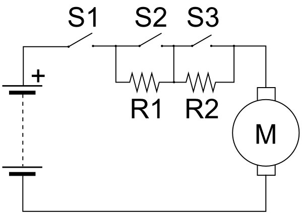
In connection with my interest in electric vehicles, I've been looking at the technology of DC motor control. The usual way (nowadays) to do this is by PWM (Pulse-Width Modulation). However, in earlier designs, such as found in trams and trolleybuses, simple resistor controllers were used. They have some disadvantages for battery vehicles, but are easy to build and understand.
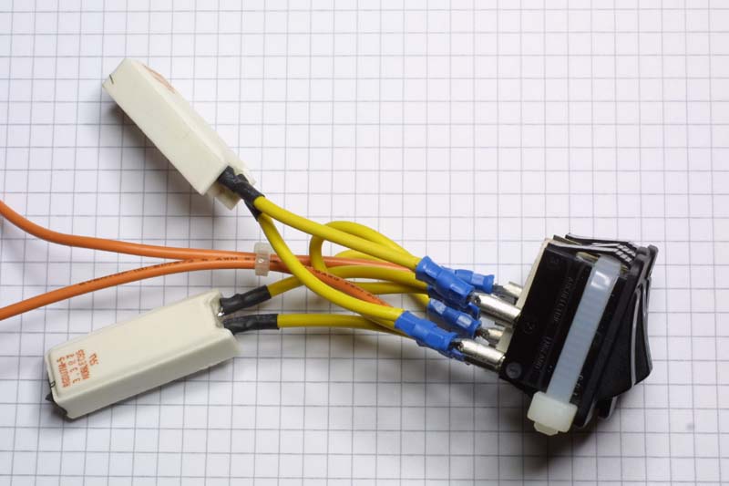
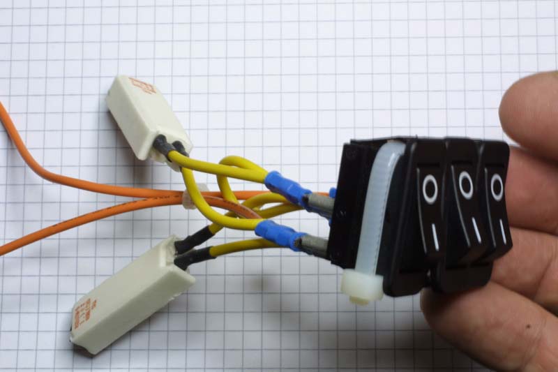
The result is a controller that works, but only has three steps instead of continuously-variable control. Tram and trolleybus controllers were built with many more steps, but still suffered from the problem of heat dissipation in the resistors. In a battery vehicle, this heat must come from the energy stored in the battery, and is therefore a symptom of wasted energy. Another snag with this design is that the resistors need to be located somewhere where the heat can be dissipated, but the switches need to be located at the driving position. This can lead to very complicated wiring and remote-control problems.
A much better solution is to rapidly switch the power supply to the motor on and off. If the "on" periods are equal to the "off" periods, one could think of the average motor current being half (50%) of the full "on" current. If the "on" periods are much smaller than the "off" periods, then we get a lower average current. Longer "on" periods and shorter "off" periods will give us higher average current, up to the normal level when the motor is directly connected to the battery. By varying the ratio of "on" time to "off" time, we can get continuously variable control.
So, we need a switch that can be switched on and off many thousands of times per second, a speed which rules out the practical use of a mechanical switch. Fully electronic switches can, of course, be made. An ordinary bipolar transistor may be used as a switch, for instance. But at high current levels, a more efficient switch can be made using a MOSFET (Metal Oxide Semiconductor Field-Effect Transistor). This transistor can be switched on and off very rapidly (millions of times per second), has a very low resistance when "on" and can handle the large currents required for big motors.
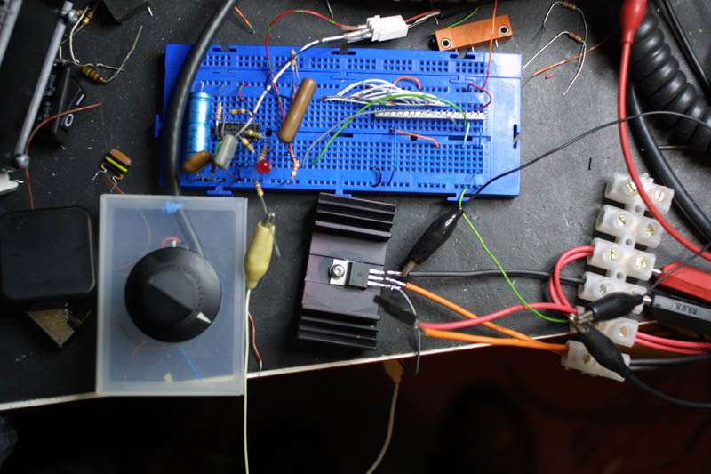
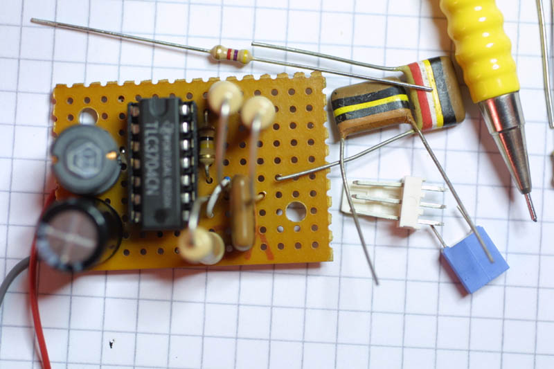
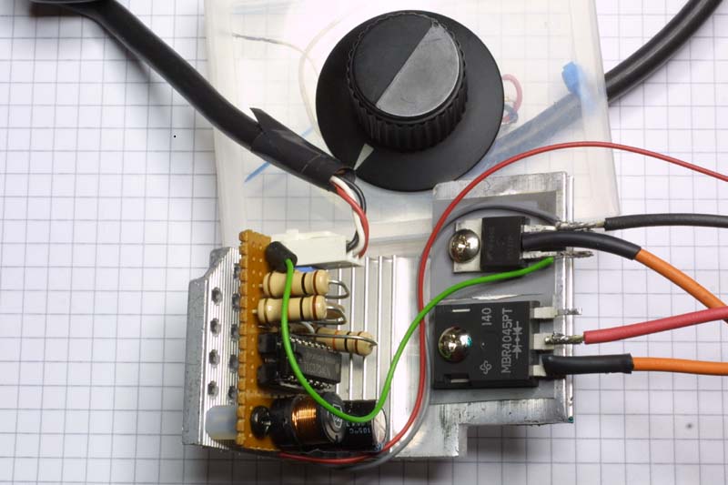
To generate the variable mark/space ratio square wave, I used a Texas Instruments TLC3704 comparator chip (actually four comparators in one 14-pin package). The data sheet for this chip includes a circuit diagram (schematic) for a PWM motor controller. I used this circuit almost directly, but had to correct a mistake where the two inputs to one comparator were swapped, which meant that the original circuit didn't oscillate. Another factor in my choice was that I had a bag full of these chips that I'd got from FreeCycle a little while ago. For the output switching MOSFET, I used the Fairchild HUF75337. This MOSFET is rated at 75A, 55V and 0.014Ω on-resistance; it's also available from Maplin's. There's also an MBR4045 diode for back-EMF protection; this was salvaged from a dead PC power supply, along with a handy heatsink. I added a 5kΩ linear pot in a box to act as a throttle control. When powered from a 12V lead-acid battery, the circuit can control a 400W Bosch GPA motor, without the heatsink getting hot.
The two controllers were used to demonstrate motor control for a talk at the Battery Electric Vehicles of Bristol group meeting. Larger versions of the photos are available in this Flickr set.
Return to the Creative Technology page
Return to John Honniball's home page
Copyright © 2007-2008 by John Honniball. All rights reserved.