
Another advantage of using the larger AVR chip is that there are still more devices to choose from that fit the same basic chip pinout. Going up the scale from the ATmega32, there's the ATmega644, which has more memory as well as extra I/O devices. The pinout is much the same, for all these 40-pin DIL chips, so one PCB should work for all of them. Another advantage of the new chips is that they have two serial ports, which makes applications like serial protocol convertors possible.
This list summarises the design goals for this board, in no particular order:
One thing I didn't do was add the dual RS-232 buffer chip. The reason was rather silly: my offcut of copper-clad PCB material was too small to build the complete board! I left off about a fifth of the design, which meant that I had to omit the MAX232 or MAX220 chip. Of course, the Atmel AVR chip still has the serial ports in it, so I can add an off-board level shifter if and when required. I could even build a level shifter chip into a 9-pin "D" connector.
The final design was done using the free GNU PCB program and then printed onto junk-mail paper with an HP LaserJet 4+ printer. The toner from that printing was then transferred to the copper-clad board with a hot domestic smoothiing iron and the paper was soaked in warm water to remove it, leaviing the board ready to etch. Etching was done with ferric chloride in the usual way, and then the toner was removed with acetone, leaving the board ready to drill. I drilled most of the holes to 0.8mm diameter, but some of them needed to be a little larger, 1.0mm. The larger size was needed for the I/O connectors, the two-pin power connector, the reset switch and the six-pin programming header.
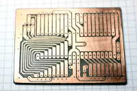
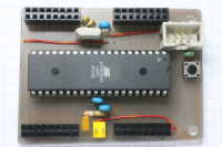
Having completed the board, of course I have found a number of mistakes in the design. The main problems are with clearances; I just didn't leave enough room around the 16-pin I/O connectors. The placement of one of the wire links ended up underneath the six-pin programming header, which requires a little care in assembly to fit that wire first. The four I/O connectors look good, but if I was to build a board that used all of them and plugged in on top of the AVR board, all sorts of things would get in the way. It would be much better to keep the area clear for plug-ins and move the power connector, programming header and power-on LED out to the ends of the board.
The 15mil (15 thousandths of an inch) tracks have worked perfectly, connecting the six-pin programming header to the proper pins on the AVR chip. I didn't need to use the wire links to make those connections. The pull-up resistor for RESET fits OK under the AVR chip's socket, even if it is a bit of a kludge.
More photos of the PCB and the etching process are in this Flickr set, and photos of the final board are in this Flickr set.
Bill of Materials
| Qty | Description | Manufacturer's Part Number | Farnell Order Code | RS Order Code |
|---|---|---|---|---|
| 1 | ATmega32 Microcontroller | Atmel ATMEGA32-16PU | 917-1282 | |
| 1 | 40-pin DIL Socket | Multicomp 2227MC-40-06-05-F1 | 110-3855 | |
| 1 | 16MHz Crystal, HC49/S | IQD LF A161K | 971-3700 | |
| 2 | 22pf ceramic capacitor | Multicomp 2222 680 34229 | 113-8845 | |
| 3 | 100nf ceramic capacitor | Multicomp MCRR25104X7RK0050 | 121-6438 | |
| 1 | 10nf ceramic capacitor | |||
| 1 | 6-way 0.1-inch Header | Harting 09 18 506 7324 | 109-6984 | |
| 4 | 16-way 0.1-inch Female Header | Multicomp 2214S-16SG-85 | 159-3492 | |
| 1 | 2-pin KK Header | Molex 22-27-2021 | 973-1148 | |
| 1 | Rectangular amber LED | |||
| 1 | 390Ω resistor | |||
| 1 | 10kΩ resistor | |||
| 1 | Pushbutton switch |
| Qty | Description | Manufacturer's Part Number | Farnell Order Code | RS Order Code |
|---|---|---|---|---|
| 1 | ATmega324P Microcontroller | Atmel ATMEGA324P-20PU | 145-5110 | |
| 1 | 20MHz Crystal, HC49/S | Vishay Dale XT49S 20M XT49S-20 B04 E2 | 146-9646 |
Return to the Creative Technology page
Return to John Honniball's home page
Copyright © 2008 by John Honniball. All rights reserved.