Nearly all CD-ROM drives have a brushless DC motor to spin the CD. This type of motor is used because a CD-ROM drive requires accurate speed control (for fast reading speed) and high torque (for fast start-up). Brushless DC motors are also used in model aeroplanes and helicopters due to their good power-to-weight ratio.
These brushless DC motors are generally a three-phase design, but there are two different ways to design them, one with a set of Hall-effect sensors for commutation, and the other without. This project relies on the use of a recycled motor with Hall-effect sensors in it. I found one in a scrap CD-ROM drive fairly easily, and also salvaged the FPC ribbon cable and connector from the drive (makes wiring-up a bit easier).
A Hall-effect sensor has four terminals; two terminals are used to pass a small current through the device, while two more are used to sense the voltage output of the device. This output voltage is usually very small, a few millivolts, and in the CD-ROM drive, this output is connected to the motor driver chip. The driver chip then uses the sensor data to energise the three coils of the motor in the proper sequence.
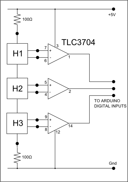
My plan was to utilise the three hall-effect sensors to sense rotation of the motor, but not rotation under power. Instead, I wanted to sense manual rotation of the CD-ROM hub. The voltage produced by a Hall-effect sensor is proportional to the strength of the magnetic field, but all we actually need in this circuit is to know its polarity. The polarity reverses each time the magnets in the rotating part of the motor go past a sensor. So, we can connect a comparator chip to the Hall-effect sensors, and since we can get quad comparator chips, one chip will be sufficient for all three sensors. I used a TLC3704, simply because I have lots of them that I got from FreeCycle. The comparator outputs will go from TRUE to FALSE and back again as the magnets rotate past the sensors. The three sensors are arranged by the design of the motor so that they go on and off in the following pattern:
| FALSE | FALSE | FALSE |
| TRUE | FALSE | FALSE |
| TRUE | TRUE | FALSE |
| TRUE | TRUE | TRUE |
| FALSE | TRUE | TRUE |
| FALSE | FALSE | TRUE |
But what about the motor? So far, it has been turned by the user, not under its own power. Can we do anything with the motor to simulate the ‘feel’ of a control? Can we make it simulate click-stops, for instance? Well, that will need a triple-half-H-bridge driver circuit!
Return to the Creative Technology page
Return to John Honniball's home page
Copyright © 2009-2011 by John Honniball. All rights reserved.